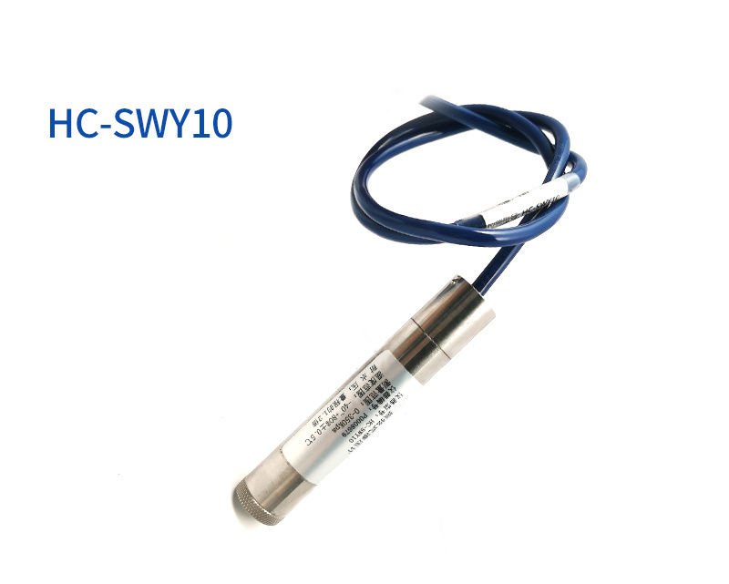
Soil Multi-Parameter Transmitter
Category:
keyword:
Product introduction
Product Overview
This sensor has stable performance and high sensitivity, and is an important tool for observing and studying the occurrence, evolution, improvement, and water and salt dynamics of saline-alkali soil. By measuring the dielectric constant of the soil, it can directly and stably reflect the actual water content of various soils. It can measure the volume percentage of soil moisture, which is a soil moisture measurement method that meets the current international standards.
This sensor is suitable for soil moisture monitoring, scientific experiments, water-saving irrigation, greenhouse, flowers and vegetables, grassland and pastures, soil quick test, plant culture, sewage treatment, precision agriculture and other occasions.
Functional features
Soil water content, electrical conductivity and temperature three parameters in one.
It can also be used for the electrical conductivity of water-fertilizer integrated solutions, and other nutrient solutions and substrates.
The electrode is made of specially treated alloy material, which can withstand strong external impact and is not easy to damage.
Completely sealed, resistant to acid and alkali corrosion, can be buried in soil or directly placed in water for long-term dynamic testing.
High precision, fast response, good interchangeability, probe plug-in design ensures precise measurement, reliable performance.
|
|
Product selection
|
RS- |
Company code |
|||
|
ECTH- |
Electrical Conductivity Temperature Moisture Three-in-One Transducer |
|||
|
ECH- |
Soil moisture sensor with conductivity |
|||
|
N01- |
RS485 (ModBus-RTU protocol) |
|||
|
TR-1 |
Soil testing shell |
|||
Dimensions
How to use
Equipment size diagram (unit: mm)
Since the electrical conductivity of soil solution ions is measured directly by the electrode, the soil volumetric water content needs to be higher than about 20% for the soluble ions in the soil to correctly reflect the electrical conductivity of the soil. Measurement values after irrigation or rainfall are closer to the true level during long-term observation. If a quick test is to be conducted, it is possible to water the soil to be measured first and then measure after the water has fully penetrated.
When measuring on a harder surface, a hole should be drilled (the hole diameter should be smaller than the probe diameter) first, and then the soil should be compacted and the sensor should be inserted into the soil and then measured; the sensor should be prevented from violent vibration and impact, and should not be knocked with a hard object. Since the sensor is encapsulated in black, it will heat up sharply under strong sunlight (it can reach more than 50℃), in order to prevent the temperature from being too high and affecting the temperature measurement of the sensor, please pay attention to shade and protection when using it in the field or outdoors.
Quick test method
Select a suitable measurement site, avoid stones, ensure that the steel needle does not touch hard objects, throw away the topsoil according to the required measurement depth, keep the original hardness of the soil below, grip the sensor and insert it vertically into the soil, do not shake it left and right when inserting, and it is recommended to take multiple measurements in a small range of a measurement point to find the average.
Trenching Survey Method
Dug a vertical pit with a diameter of >20cm, inserted the sensor steel needle horizontally into the pit wall at the specified depth, backfilled the pit tightly, and after a period of stability, the measurement and recording can be carried out continuously for several days, months, or even longer.
Notes
1. The steel needle must be completely inserted into the soil during measurement.
2、Avoid direct sunlight on the sensor to prevent overheating. Be aware of lightning strikes when using in the field.
3、Do not bend the steel needle violently, do not pull the sensor lead wire hard, do not drop or strike the sensor hard.
4、Sensor protection grade IP68, the sensor can be completely soaked in water.
5、Since there is radio frequency electromagnetic radiation in the air, it is not suitable to be in the air for a long time with the power on.
Equipment installation instructions
Inspection before equipment installation
Equipment list:
Sensor device 1 unit
Certificate of Conformity, Warranty Card, Wiring Instructions, etc.
USB
Turn
485
( optional )
Interface description
Wide voltage power input 4.5~30V is available. When connecting the 485 signal line, note that the A/B two lines cannot be connected in reverse, and the addresses of multiple devices on the bus cannot conflict.
Wiring instructions
|
Color line |
Explanation |
Note |
|
Brown |
Power positive |
4.5~30V DC |
|
Black |
Power ground |
GND |
|
Yellow |
485-A |
485-A |
|
Blue |
485-B |
485-B |
Configuration software installation and use
Software selection
Open the data package, select "Debug Software"---"485 Parameter Configuration Software", find and open it.
Parameter setting
①、Select the correct COM port ("My Computer-properties-device Manager-ports" to view the COM ports), the following figure lists the drive name of several different 485 converters.
②、Connect only one device and power it on, click the test baud rate in the software, the software will test the current device's baud rate and address, the default baud rate is 4800bit/s, the default address is 0x01.
③、Modify the address and baud rate according to the use needs, and you can also query the current functional status of the device.
④、If the test is not successful, please re-check the equipment wiring and 485 drive installation.
Communication protocol
Basic parameters of communication
|
Coding |
8-bit binary |
|
Data bit |
8-bit |
|
Parity bit |
None |
|
Stop bit |
1 person |
|
Error checking |
CRC (Cyclic Redundancy Code) |
|
Baud rate |
Optional, the factory default is 4800 bit/s |
Data frame format definition
Adopt ModBus-RTU communication protocol, the format is as follows: Initial structure ≥4 bytes of time
Address code = 1 Byte Function code = 1 Byte Data area = N Bytes
Error checking = 16 bit CRC code end structure ≥4 byte time
Address code: The address of the transducer, which is unique in the communication network (factory default 0x01). Function code: Indicator of the function of the command issued by the host.
Data Area: The data area is specific communication data, note that the high byte of 16-bit data is in front!
CRC code: A two-byte checksum. Host inquiry frame structure:
From the machine response frame structure:
|
Address code |
Function code |
Number of effective bytes |
Data area one |
Data two area |
Data N District |
Check code low byte |
Check code high byte |
|
1 Byte |
1 Byte |
1 Byte |
2 bytes |
2 bytes |
2 bytes |
1 Byte |
1 Byte |
Register address
|
Register address |
PLC or configuration address |
Content |
Operation |
Definition explanation |
|
0000 H |
40001 (decimal) |
Moisture content |
Read-only |
Real-time water content value (enlarged 10 times) |
|
0001 H |
40002 (decimal) |
Temperature value |
Read-only |
Real-time temperature value (enlarged 10 times) |
|
0002 H |
40003 (decimal) |
Electrical conductivity |
Read-only |
Real-time conductivity value |
|
0003 H |
40004 (decimal) |
Salinity |
Read-only |
Salinity real-time value |
|
0004 H |
40005 (decimal) |
Total Dissolved Solids TDS |
Read-only |
TDS real-time value |
|
0022 H |
40035 (decimal) |
Electrical conductivity temperature coefficient |
Reading and writing |
0-100 corresponds to 0.0%-10.0% Default 0.0% |
|
0023 H |
40036 (decimal) |
Salinity coefficient |
Reading and writing |
0-100 corresponds to 0.00-1.00 Default 55 (0.55) |
|
0024 H |
40037 (decimal) |
TDS coefficient |
Reading and writing |
0-100 corresponds to 0.00-1.00 Default 50 (0.5) |
|
0050 H |
40081 (decimal) |
Temperature calibration value |
Reading and writing |
Integers (expanded by 10) |
|
0051 H |
40082 (decimal) |
Calibration value of water content |
Reading and writing |
Integers (expanded by 10) |
|
0052 H |
40083 (decimal) |
Conductivity calibration value |
Reading and writing |
Integer |
|
07D0 H |
42001 (decimal) |
Equipment address |
Reading and writing |
1~254 (factory default 1) |
|
07D1 H |
42002 (decimal) |
Equipment Baud Rate |
Reading and writing |
0 stands for 2400 1 represents 4800 2 represents 9600 |
Note: The conductivity moisture device does not have a temperature value and its calibration value register.
Communication protocol examples and explanations
Example: Reading the conductivity temperature moisture three-in-one device (address
0x01
Electrical conductivity and temperature moisture values of )
Inquiry frame
Response frame
|
Address code |
Function code |
Return valid Number of bytes |
Moisture value |
Temperature value |
Conductivity value |
Check code Low byte |
Check code High Byte |
|
0x01 |
0x03 |
0x06 |
0x02 0x92 |
0xFF 0x9B |
0x03 0xE8 |
0xD8 |
0x0F |
Temperature calculation:
When the temperature is lower than 0 ℃, the temperature data is transmitted in complement form. Temperature: FF9B H (hexadecimal) = -101 => Temperature = -10.1 ℃ Moisture calculation:
Water content: 292 H (hexadecimal) = 658 => Relative humidity = 65.8%, i.e. soil volume water content is 65.8%. Conductivity calculation:
Conductivity: 3E8 H (hexadecimal) = 1000 => Conductivity = 1000μS/cm
Frequently Asked Questions and Solutions
Equipment cannot be connected to PLC or computer
Possible reasons:
The computer has multiple COM ports, the selected port is incorrect.
Device address error, or there is a device with duplicate address (all factory defaults are 0x01).
Baud rate, parity method, data bits, stop bits error.
Bus 485 is broken, or lines A, B are reversed.
Too many devices or too long wiring, power should be supplied nearby, add 485 booster, and increase 120Ω termination resistor.
USB to 485 driver is not installed or damaged.
Equipment damage.
Technical parameters
|
DC power supply (default) |
DC 4.5-30V |
|
|
Maximum power consumption |
0.7W(24V DC power supply) |
|
|
Working temperature |
-40℃~+60℃ |
|
|
Core chip temperature resistance |
85℃ |
|
|
Conductivity parameter |
Range |
0-20000μS/cm |
|
Resolution |
10μS/cm |
|
|
Precision |
0-10000μS/cm range is±3%FS; 10000-20000μS/cm range is ±5%FS (Brown soil,60% RH, 25℃) |
|
|
Soil moisture parameters |
Range |
0-100% |
|
Resolution |
0.1% |
|
|
Precision |
0-50%in±2%,@( brown soil,30%,25℃) 50-100%in±3%,@(chernozem,60%,25℃) |
|
|
Soil temperature parameter |
Range |
-40~80℃ |
|
Resolution |
Resolution:0.1℃ |
|
|
Precision |
±0.5℃(25℃) |
|
|
Electrical conductivity temperature compensation |
Built-in temperature compensation sensor, compensation range 0-50℃ |
|
|
Protection level |
IP68 |
|
|
Probe material |
Anti-corrosion special electrode |
|
|
Sealant material |
Black flame retardant epoxy resin |
|
|
Default cable length |
2m, cable length can be customized as required |
|
Dimensions |
45*15*123mm |
|
Output signal |
RS485(ModBus protocol) |
Soil Multi-Parameter Transmitter PRODUCT SPECIFICATION
Related products
Related products
Welcome to leave a message for consultation
Welcome to leave a message for consultation

 Inquiry