
 Inquiry
 Water Quality Sensor")
Multi-parameter(5 in 1) Water Quality Sensor
Category:
keyword:
Optional equipment technical parameters
|
pH sensor |
|
|
Measurement range |
0~14pH |
|
Measurement accuracy |
±0.1pH |
|
Resolution |
0.01pH |
|
Dissolved oxygen sensor |
|
|
Measurement range |
0~20mg/L |
|
Measurement accuracy |
±2% F.S. |
|
Resolution |
0.01mg/L |
|
Turbidity sensor |
|
|
Measurement range |
0~1000NTU |
|
Measurement accuracy |
±5% F.S. |
|
Resolution |
0.1NTU |
|
Conductivity/ salinity sensor |
|
|
Measurement range |
0~5000uS/cm |
|
Measurement accuracy |
±1.5% F.S. |
|
Resolution |
1uS/cm |
|
Temperature |
|
|
Measurement range |
0~50℃ |
|
Precision |
±0.3℃ |
|
Resolution |
0.1℃ |
|
Other information on multi-parameter sensors |
|
|
Output mode |
RS-485(Modbus/RTU) |
|
Cleaning method |
Automatic cleaning |
|
Supply voltage |
12V-24DC±5% |
|
Cable length |
Standard 10 meters, other lengths can be customized |
Size chart
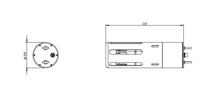
Note: The sensor is measured with the use of a hanger or pipe thread installation when installing the sensor, avoiding the cable from being directly stressed.
Sensor connector is M16-4 core waterproof connector male.
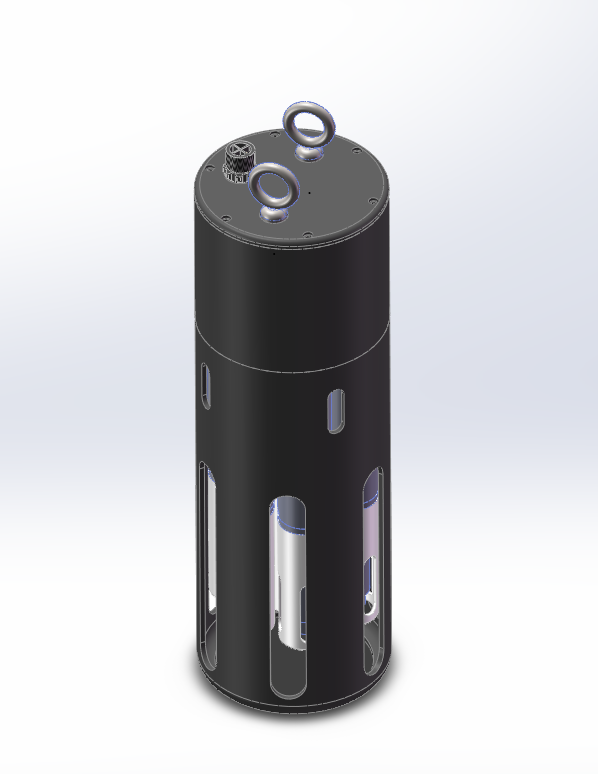
Product Introduction
Online multi-parameter self-cleaning digital sensor, with integrated design, reliable and easy to use. Up to 7 parameters can be measured simultaneously, and the sensor types that can be selected include dissolved oxygen, pH, ORP, conductivity/salinity, turbidity, etc. With RS-485 bus and Modbus/RTU communication protocol, data can be directly transmitted to the collection platform.
The online multi-parameter water quality sensor is equipped with an automatic cleaning device, which can set the automatic cleaning interval time and the number of automatic cleaning circles to adapt to different cleaning degrees of water quality. The automatic cleaning device can effectively clean the sensor surface, prevent microbial attachment, and greatly reduce maintenance costs. Each sensor is equipped with a quick plug and play waterproof connector, which is convenient to disassemble and assemble.
The front sensor cover is used to protect the internal sensor from damage, and the cover is provided with grooves around it to effectively prevent large suspended particles and organisms from destroying the sensor probe, without affecting the accuracy of the measurement.
Sensor features:
Digital sensor, RS-485 bus, Modbus/RTU communication protocol.
Equipped with an automatic cleaning device, it can effectively clean the sensor surface, prevent microbial attachment, and measure more accurately, with lower maintenance costs.
Optional dissolved, conductivity/salinity, turbidity, pH, ORP and other digital sensors, suitable for long-term online monitoring.
Integrated design, can measure 7 parameters simultaneously (including temperature)
Electrical connection
The cable is a 4-core twisted shielded wire, and the wire sequence definition:
Red line—power line (12~24VDC)
Black line — Ground (GND)
Blue line—485A
White line—485B
Bare wire—屏蔽 layer
The sequence of wiring should be carefully checked before power is applied to avoid unnecessary loss due to wiring errors.
Wiring instructions: considering that the cables will be soaked in water (including seawater) or exposed to the air for a long time, all wiring points are required to be waterproofed, and the user cables should have certain corrosion resistance.
Maintenance and care
5.1 Maintenance schedule
The online multi-parameter self-cleaning water quality sensor is equipped with a cleaning brush, which can extend the maintenance cycle. Due to the diversity of the environment, it is recommended to regularly check, clean and calibrate the sensor.
|
Maintenance tasks |
Recommended maintenance frequency |
|
Clean sensor |
Depends on the environment of use |
|
Calibrate sensor (if necessary) |
Calibration of sensors regularly |
5.2 Calibration maintenance method of sensor
Check: Check if the sensor head is dirty and if there is any microbial attachment, if the housing and sensor surface are damaged, if the cables are normal, if the test data is normal, if the consumables are damaged.
Cleaning: wash the outer surface of the sensor with tap water, if there are still debris residues, wipe it with a moist soft cloth, for some stubborn dirt, you can add some household detergent to the tap water to clean.
Calibration: Calibrate the sensor with a single point or two points. Select the appropriate standard solution according to the corresponding sensor. For details of the calibration method, refer to the manual of the corresponding sensor.
5.3 Frequently Asked Questions
|
Error |
Possible reasons |
Solution |
|
No communication return |
Circuit integration part error |
Please contact us |
|
Cable fault |
Please contact us |
|
|
Measurement values are too high, too low, or the value is continuously unstable. |
The sensor is dirty and has microbial attachment. |
Clean the sensor surface |
|
See the常见 questions in the manual of each corresponding sensor. |
||
Quality and service
6.1 Warranty cycle
|
Dissolved oxygen sensor |
One year |
|
Turbidity sensor |
One year |
|
Conductivity/ salinity sensor |
One year |
|
pH sensor |
One year |
|
Online multi-parameter probe parent body |
One year |
|
Other consumables |
One year |
6.2 Accessories and spare parts
This product includes:
Sensor 1 piece
Instructions 1 copy
Certificate of Conformity 1 copy
Appendix Data Communication
Data format
The default data format for RS-485 communication is: 9600, n, 8, 1 (baud rate 9600 bps, 1 start bit, 8 data bits, no parity, 1 stop bit).
Information frame format (xx represents a byte)
Read data command frame
06 03 xx xx xx xx xx
Address Function Code Register Address Register Quantity CRC Checksum (Low Byte First)
Read Data Response Frame
06 03 xx xxxxx xxxxx xxxxx xxxxx xxxxx
Address Function Code Number of Bytes Response Data CRC Checksum (Low Byte First)
Write data command frame
06 06 xx xx xx xx xx xx
Address Function Code Register Address Data Written CRC Checksum (LSB first)
Write Data Response Frame (Same as Write Data Command Frame)
06 06 xx xx xx xx xx xx
Address Function Code Register Address Data Written CRC Checksum (LSB first)
Register address
|
Register address |
Name |
Explanation |
Number of registers (bytes) |
Access mode (function code) |
|
0x0100 |
Temperature measurement value |
1 double word integer representing the temperature value. |
1 (2 bytes) |
Read (0x03) |
|
0x0101 |
DO measurement value |
1 double word integer, representing the DO value. |
1 (2 bytes) |
Read (0x03) |
|
0x0102 |
Turbidity measurement value |
1 double byte integer representing the turbidity value. |
1 (2 bytes) |
Read (0x03) |
|
0x0103 |
pH measurement value |
1 short integer, representing the pH value. |
1 (2 bytes) |
Read (0x03) |
|
0x0104 |
EC measurement values |
1 short integer, representing the EC value. |
1 (2 bytes) |
Read (0x03) |
|
0x010A |
DS state value |
1 double word integer, 1 for motor rotation. |
1 (2 bytes) |
Read (0x03) |
|
0x1000 |
Temperature calibration |
Temperature calibration: The written data is the actual temperature value x 10; the read data is the temperature calibration offset x 10. |
1 (2 bytes) |
Write(0x06)/Read(0x03) |
|
0x1001 |
DO zero point calibration |
Calibrate in anoxia water, the written data is 0; |
1 (2 bytes) |
Write(0x06)/Read(0x03) |
|
0x1002 |
DO slope calibration |
Calibration in air saturated with water or water saturated with air, the written data is 0; |
1 (2 bytes) |
Write(0x06)/Read(0x03) |
|
0x1003 |
Turbidity zero point calibration |
Calibrate in deionized water or standard solution of 0~20.0NTU, the written data is the turbidity value of the standard solution ×10; |
1 (2 bytes) |
Write(0x06)/Read(0x03) |
|
0x1004 |
Turbidity slope calibration |
Calibration in the 200.0~1000.0NTU standard solution, the data written is the turbidity value of the standard solution ×10; |
1 (2 bytes) |
Write(0x06)/Read(0x03) |
|
0x1005 |
pH zero calibration |
Calibrated in a standard solution at pH 6.86, the written data is 0; the read data is the zero drift. |
1 (2 bytes) |
Write(0x06)/Read(0x03) |
|
0x1006 |
pH slope calibration (4pH/9pH) |
Calibration in standard solution at pH 4.00, written data is 0; calibration in standard solution at pH 9.18, written data is 1; read data is slope value x 1000. |
1 (2 bytes) |
Write(0x06)/Read(0x03) |
|
0x1007 |
Electrical conductivity zero point calibration |
Calibration in air, write data is 0; read data is zero point offset. |
1 (2 bytes) |
Write(0x06)/Read(0x03) |
|
0x1008 |
Electrical conductivity slope calibration |
Calibrated in standard solution, full scale is 0~5000μS/cm, the data written is the actual value of the standard solution; full scale is 0~200mS/cm, the data written is the actual value of the standard solution ×10; full scale is 0~70PSU, the data written is the actual value of the standard solution ×10. The data read is the slope value ×1000. |
1 (2 bytes) |
Write(0x06)/Read(0x03) |
|
0x3000 |
Automatic cleaning interval setting |
Default is 30 minutes, data range 6 to 6000 minutes. |
1 (2 bytes) |
Write(0x06)/Read(0x03) |
|
0x3001 |
Number of automatic cleaning circles set |
Default is 3 turns, data range 0 to 10 turns. |
1 (2 bytes) |
Write(0x06)/Read(0x03) |
|
0x3002 |
Brush manual control |
Enter data range 0~10 circles. |
1 (2 bytes) |
Write(0x06)/Read(0x03) |
|
0x2002 |
The address of the sub-sensor corresponding to the temperature data |
The default data is 4, which can be 1, 4, 8, 32, 64, 65, etc. |
1 (2 bytes) |
Write(0x06)/Read(0x03) |
|
0x2000 |
Sensor address |
Default to 01, data range 1 to 255. |
1 (2 bytes) |
Write(0x06)/Read(0x03) |
Related products


")
")
")
Related products
Welcome to leave a message for consultation

Copyright © 2025 Xiamen Haichuan Runze Internet of Things Technology Co.,Ltd. ALL Rights Reserve.
Welcome to leave a message for consultation