
 Inquiry
Wind Direction Transmitter-8
Category:
keyword:
1. Product Introduction
1.1 Product Overview
HC-FX100 Wind Direction Transducer, small and lightweight, easy to carry and assemble, the new design concept can effectively obtain wind direction information, the shell is made of polycarbonate composite material, which has good corrosion resistance, erosion resistance and other characteristics, can ensure that the transducer is not deformed for a long time, and at the same time, the internal smooth bearing system ensures the accuracy of information collection. It is widely used in greenhouse, environmental protection, meteorological station, ship, wharf, breeding and other wind direction measurement in the environment.
1.2 Features
Range: 8 directions of indication
Anti-electromagnetic interference treatment
High-performance imported bearings are used, with low turning resistance and precise measurement.
Polycarbonate shell, high mechanical strength, high hardness, corrosion resistance, no rust, can be used outdoors for a long time.
The equipment structure and weight are carefully designed and distributed, with a small moment of inertia and quick response.
Standard ModBus-RTU communication protocol, easy to access
2. Equipment installation instructions
2.1 Inspection before equipment installation
Equipment list:
■ Transducer equipment 1 unit
■Installation screws 4 pieces
■Certificate of Conformity, Warranty Card, Wiring Instructions, etc.
■USB to 485 (optional)
■485 Terminal resistor (optional)
2.2 Interface Description
Wide voltage power input of 10~30V is available. When connecting the 485 signal line, note that the A\B two lines cannot be connected in reverse, and the addresses of multiple devices on the bus cannot conflict.
Electrical wiring
|
Color line |
Explanation |
|
|
Power supply |
Brown |
Power positive (10~30V DC) |
|
Black |
Power negative |
|
|
Communication |
Yellow (green) |
485-A |
|
Blue |
485-B |
2.4 On-site wiring instructions
When multiple devices of 485 model are connected to the same bus, there are certain requirements for field wiring, please refer to the "485 Device Field Wiring Manual" in the reference package.
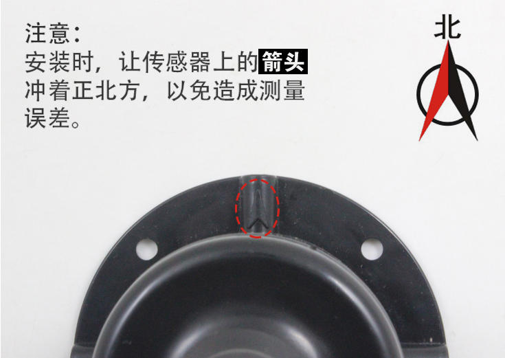
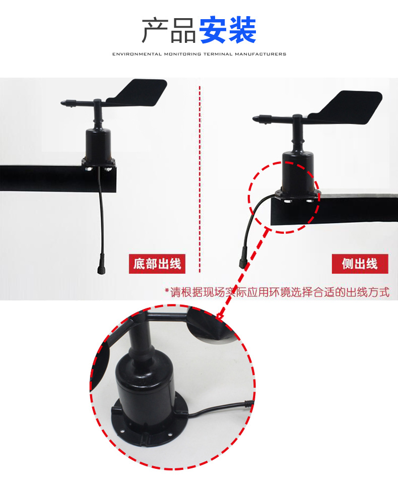
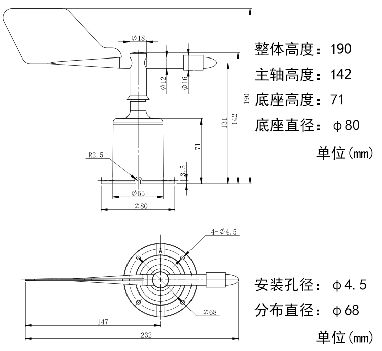
2.5 Installation method
The wind direction sensor is firmly fixed to the flange by means of a threaded flange connection, the base Ø80mm, with four mounting holes Ø4.5mm evenly distributed on the circumference of Ø68mm, which are tightly secured to the bracket with bolts, ensuring that the entire instrument maintains the best levelness, ensuring the accuracy of the wind direction data, the flange connection is convenient to use and can withstand a large pressure.
2.6 Notes on Precautions
1. Users are not allowed to disassemble by themselves, and must not touch the sensor core, to avoid damage to the product.
2. Try to stay away from high-power interference devices to avoid inaccurate measurement, such as frequency converters, motors, etc. When installing and dismantling the transmitter, the power supply must be cut off first. Water entering the transmitter can cause irreversible changes.
3. Prevent chemical reagents, oil, dust, etc. from directly affecting the sensor, do not use it for a long time in a dew point environment, and strictly prevent sudden cold and heat.
3. Software installation and configuration;
3.1 Software selection
Open the data package, select "Debug Software"---"485 Parameter Configuration Software", find
Open it.
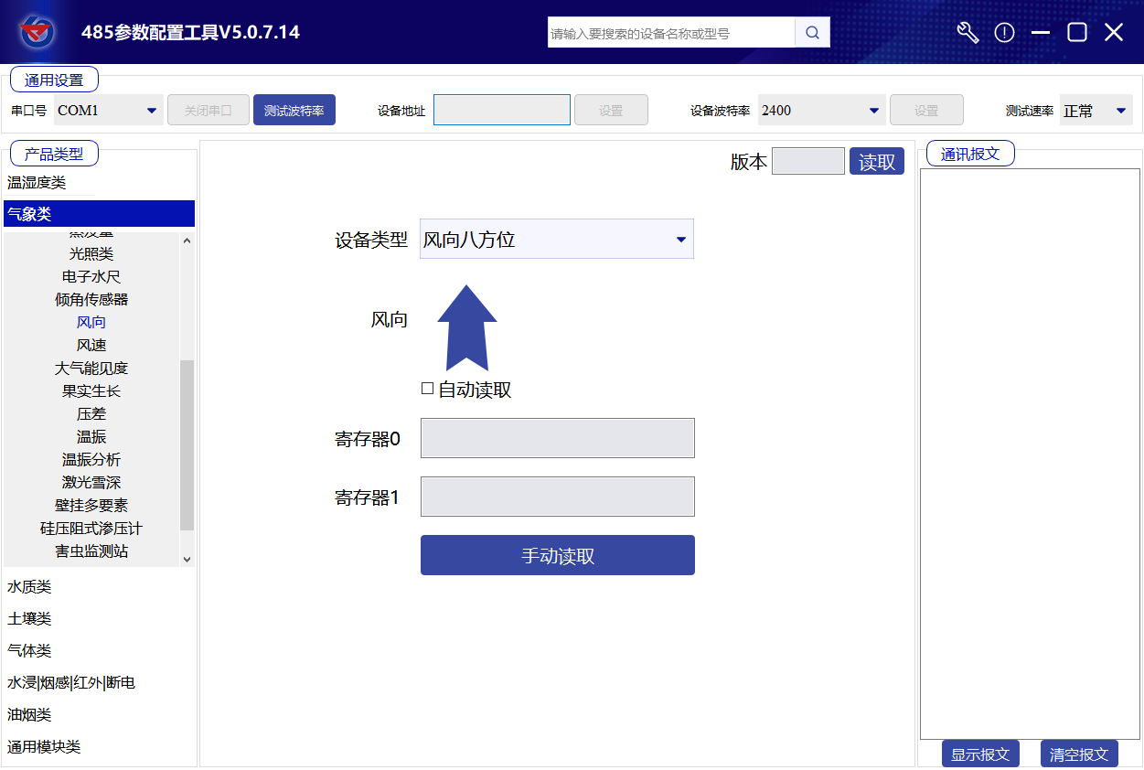
3.2 Parameter setting
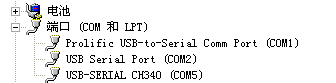
①、Select the correct COM port ("My Computer - Properties - Device Manager - Ports" to view the COM ports), the following figure lists the drive name of several different 485 converters.
②、Connect only one device and power it on, click the test baud rate in the software, the software will test the current device's baud rate and address, the default baud rate is 4800bit/s, the default address is 0x01.
③、Modify the address and baud rate according to the use needs, and at the same time, you can query the current functional status of the device.
④、If the test is not successful, please re-check the equipment wiring and the installation of the 485 driver.
4. Communication protocol
4.1 Basic parameters of communication
|
Encoding |
8-bit binary |
|
Data bit |
8-bit |
|
Parity bit |
None |
|
Stop bit |
1 person |
|
Error checking |
CRC (Cyclic Redundancy Code) |
|
Baud rate |
2400bit/s, 4800bit/s, 9600 bit/s can be set, the factory default is 4800bit/s |
4.2 Data Frame Format Definition
Adopt ModBus-RTU communication protocol, format as follows:
Initial structure ≥4 bytes time
Address code = 1 byte
Function code = 1 byte
Data area = N bytes
Error checking = 16 bit CRC code
End structure ≥4 bytes time
Address code: The address of the transducer, which is unique in the communication network (factory default 0x01).
Function code: The function code indicates the command issued by the host, and this transducer only uses function code 0x03 (read register data).
Data area: The data area is specific communication data, note that the high byte of 16-bit data is in front!
CRC code: a two-byte checksum.
Host Inquiry Frame Structure:
|
Address code |
Function code |
Register start address |
Register length |
Check code low order |
Check code high bit |
|
1 byte |
1 byte |
2-byte |
2-byte |
1 byte |
1 byte |
From the machine response frame structure:
|
Address code |
Function code |
Number of effective bytes |
Data area one |
Second data area |
The Nth data area |
Check code |
|
1 byte |
1 byte |
1 byte |
2-byte |
2-byte |
2-byte |
2-byte |
4.3 Register address
|
Register address |
PLC or configuration address |
Content |
Operation |
|
0000 H |
40001 |
Wind direction (0-7) Uploading data is the true value |
Read-only |
|
0001 H |
40002 |
Wind direction (0-360°) Uploading data is the true value |
Read-only |
4.4 Numerical Corresponding Conversion Relationship
|
Collect value (0-7 scale) |
Acquisition value (0-360°) |
Corresponding direction |
|
0 |
0° |
North wind |
|
1 |
45° |
Northeast wind |
|
2 |
90° |
East wind |
|
3 |
135° |
Southeast wind |
|
4 |
180° |
South wind |
|
5 |
225° |
Southwest wind |
|
6 |
270° |
West wind |
|
7 |
315° |
Northwest wind |
4.5 Example of communication protocol and explanation
Example: Reading the wind direction from device address 0x01
Inquiry Frame:
|
Address code |
Function code |
Start address |
Data length |
Check code low order |
Check code high bit |
|
0x01 |
0x03 |
0x00 0x00 |
0x00 0x02 |
0xC4 |
0x0B |
Response frame: (for example, the wind direction value (0-7) is read as 2, (0-360°) is 90°)
|
Address code |
Function code |
Return the number of valid bytes |
Wind direction (0-7 band) |
Wind direction (0-360°) |
Check code low order |
Check code high bit |
|
0x01 |
0x03 |
0x04 |
0x00 0x02 |
0x00 0x5A |
0xDB |
0xC8 |
Wind direction calculation:
(0-7 levels): 0002H (hexadecimal) = 2 => Wind direction = East wind
(0-360°): 005AH (hex) = 90=; Wind direction= East
5. Frequently Asked Questions and Solutions
5.1 Equipment cannot be connected to PLC or computer
Possible reasons:
1) The computer has multiple COM ports, the selected port is incorrect.
2) Device address error, or there are devices with duplicate addresses (all are 1 by default from the factory).
3) Baud rate, parity method, data bits, stop bits error.
4) The host polling interval and the waiting time for a response are too short, both need to be set to 200ms or more.
5)485 bus is broken, or A, B lines are reversed.
6) Too many devices or too long wiring, power should be supplied nearby, add 485 driver, and add 120Ω termination resistor.
7)USB to 485 driver is not installed or damaged.
8) Equipment damage.
6. Dimensions
Main technical indicators
|
DC power supply (default) |
10~30V DC |
|
Power consumption |
0.15W |
|
Transducer circuit operating temperature |
-40℃~+60℃, 0%RH~80%RH |
|
Communication interface |
485 Communication (ModBus) protocol Baud rate: 2400, 4800 (default), 9600 Data bit length: 8 bits Parity check method: None Stop bit length: 1 bit Default ModBus communication address: 1 Support function code: 03 |
|
Parameter setting |
Configure via the 485 interface using the provided configuration software |
|
Measurement range |
8 directions |
|
Dynamic response speed |
≤0.5s |
Related products


")
")
")
Related products
Welcome to leave a message for consultation

Copyright © 2025 Xiamen Haichuan Runze Internet of Things Technology Co.,Ltd. ALL Rights Reserve.
Welcome to leave a message for consultation