
 Inquiry
Vibrating wire earth pressure gauge
Category:
keyword:
Strain-gauge soil pressure meter operation manual
1. Purpose
The vibrating wire soil pressure meter is suitable for long-term measurement of the compressive stress of the soil inside earth-dams, earth-dikes, slopes, road foundations, etc., and is an effective monitoring device for understanding the changes in the soil pressure inside the measured structure, and can also measure the temperature at the embedding point simultaneously.
The structure of the vibrating wire soil pressure meter is simple and the value is stable, which is convenient to install in any occasion where long-term monitoring of the compressive stress of soil is required. The vibrating wire soil pressure meter has the function of parameter identification.
2、Specifications and main technical parameters
Notes: Frequency modulusF=Hz2×10-3
3. Structure and Working Principle
3.1 Structure
The strain-gauge soil pressure meter is composed of a back plate, a sensing plate, an observation cable, a strain gauge, and a stimulating electromagnet coil, etc.
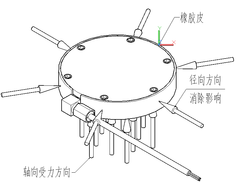
3.2 Working principle
When the soil stress in the tested structure changes, the soil pressure gauge's sensing plate synchronously senses the change in stress, the sensing plate will produce deformation, the deformation is transmitted to the vibrating wire to change the stress of the vibrating wire, thus changing the vibration frequency of the vibrating wire. The electromagnetic coil excites the vibrating wire and measures its vibration frequency, and the frequency signal is transmitted to the reading device through the cable, so the pressure stress value of the tested structure can be measured. The temperature value of the embedded point is measured synchronously.
3.3 Computing Methods
When the outside temperature is constant, the soil pressure meter is only subjected to compressive stress, and its compressive stress valuePis linearly related to the frequency modulus△Fof the output:
P = k×△F
△F= F - F0
Where:P—measured value of the soil pressure meter, unitKPa;
k—The measuring sensitivity of the soil pressure meter, the unit isKPa/F;
△F—The real-time measurement value of the soil pressure meter relative to the reference value, the phase change quantity, the unit is F;
F—Real-time measurement values of the soil pressure meter, unit F;
F0—Reference value of the soil pressure meter, unit F.
b)When the pressure stress acting on the soil pressure meter is constant, and the temperature increases△T, the soil pressure meter has an output
△F´,this output quantity is caused by the temperature change, and therefore should be deducted in the calculation. The experiment shows that △F´ and △T have the following linear relationship:
P´= k×△F´+ b×△T = 0
K×△F´= -b×△T
△T= T - T0
Where:b—Temperature correction coefficient of the soil pressure meter, unit is KPa/℃;
△T—The change amount of the real-time measurement value of temperature relative to the reference value, the unit is ℃;
T—Real-time measurement value of temperature, unit ℃;
T0—Reference value of temperature, unit ℃.
c)When the soil pressure meter is subjected to both compressive stress and temperature, the general calculation formula for the soil pressure meter is:
Pm = k×△F + b×△T= k×(F - F0)+ b×(T - T0)
Where:Pm—The value of the compressive stress of the tested structure, in units of KPa.
4、嵌入 and installation
4.1 Overview
The vibrating wire soil pressure meter is used to measure the pressure stress on the contact surface between the tested object and the soil body(interface), such as the pressure stress between the foundation of concrete buildings and the soil base; the pressure stress between the concrete lining of underground tunnels and the soil; the pressure stress between artificial slopes, walls, and piles and the soil; the pressure stress of the soil inside earth-rock dams, road bases, etc.
The soil pressure meter measures the pressure stress on the contact surface between the tested body and the soil body. Improper installation and burial methods can easily lead to the soil pressure meter detaching from the tested object and unloading, affecting the accuracy of the measurement value.
4.2埋ing method
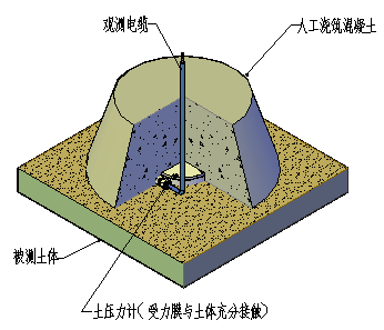
4.2.1Measuring the pressure stress on the contact surface between the foundation of a concrete structure and the soil base, the soil pressure cell is placed on the foundation soil base surface before the building base plate is poured, and it is compacted and stressed. The soil base surface must be flat, uniform, and dense, and a layer of fine sand can be evenly laid on the soil base surface to make the two contact and stressed.Sep 2.1(Fig. 4.2.1). The extension and laying of the observation cable are done well, and the concrete foundation base plate is poured.
4.2.2The soil pressure meter is installed at the bottom plate of the existing building and can be placed by digging a hole. This method is divided into precast box method: the size of the box should be 1.1 times the diameter of the soil pressure meter; Excavation pit burial method: the size of the pit should be slightly larger than the soil pressure meter, and the depth should be seen by the soil.
The requirements for the soil base surface in the hole pit are the same as above, and after all methods of installation, the soil pressure meter should be subjected to pressure or weight to fix it, extend the observation cable and lay it out. Finally, backfill the concrete(Fig. 4.2.2).
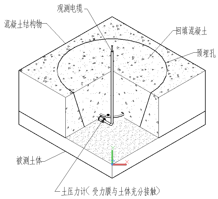
(Fig.4.2.2) Instrumentation for measuring soil pressure in the foundation
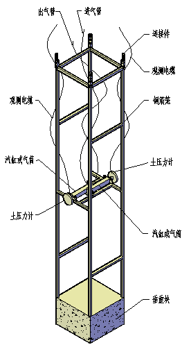
4.2.3The soil pressure meter is embedded in the concrete cut-off wall, and should be fixed on the push-cylinder first, and then fixed on the reinforcement cage. After the reinforcement cage is lowered to the bottom of the slot, the cylinder is ventilated and pressurized to push the soil pressure meter out, so that its pressure membrane surface is fully contacted with the soil on the slot wall and stressed, and then the concrete is poured to fix the soil pressure meter on the interface between the cut-off wall and the soil(Fig. 4.2.3).
4.2.4The installation of the soil pressure meter on the surface of concrete structures requires the use of an installation bracket to fix it to the monitoring surface. When installing, the sensing membrane of the soil pressure meter faces the soil, and the back is pressed against the concrete structure and fixed with expansion bolts; it can also be embedded in the concrete (Fig. 4.2.4-1).
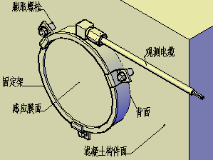
(Fig. 4.2.4-1) Method of surface embedding and fixing of the soil pressure meter
Soil pressure meters are installed on the outer surface of various concrete structure pipelines, pipe corridors, tunnel tubes, and gas pipelines in contact with the soil, and soil pressure meters can be embedded in the design position of the observation section, and the observation cable needs to be pre-embedded and protected (Fig. 4.2.4-2).
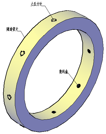
(Fig. 4.2.4-2) Schematic diagram of the installation of the soil pressure cell pipeline on the outside surface
埋设 of 土 pressure 计 at the interface between the concrete structure and the soil, which can be fixed using the pouring formwork. Before pouring, the soil pressure sensor is secured to the pouring formwork using an installation bracket. After the removal of the formwork, the residual concrete on the sensing membrane of the soil pressure sensor needs to be removed. To facilitate the removal of the residual concrete on the membrane, a layer of oil can be applied to the sensing membrane before pouring. When burying, the sensing membrane of the soil pressure sensor is in contact with the formwork, and the soil pressure sensor is secured to the formwork using three double-ended nails. The excess cable is stored in a protective box(Fig. 4.2.4-3).
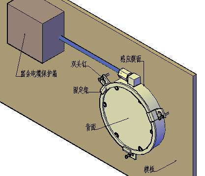
(Fig. 4.2.4-3) Schematic diagram of the installation of the soil pressure cell template
Bury the soil pressure gauge at the interface between the concrete structure and the soil, which can be fixed by the reinforcement cage. Before pouring, use the soil pressure gauge to install the bracket and fix the reinforcement bundle, which is then tied or welded to the reinforcement cage. After the formwork is removed, the residual concrete on the sensing membrane surface of the soil pressure gauge needs to be cleaned. When burying, the sensing membrane surface of the soil pressure gauge is close to the formwork, and it is not allowed to be reversed. To facilitate the removal of residual concrete on the sensing membrane surface of the soil pressure gauge, a layer of oil can be applied to the membrane surface in advance. It is necessary to do a good job in the direction and protection of the observation cable(Fig. 4.2.4-4).
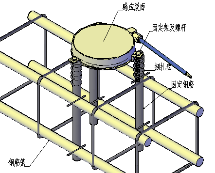
(Fig. 4.2.4-4) Schematic diagram of the installation of the soil pressure cell reinforcement cage
Bury the soil pressure meter at the contact interface between the steel structure and the soil, first weld the fixing bolts on the steel structure, and the welding position of the bolts can be determined by the installation bracket.
4.3 Laying of cables
The burial of the observation cable adopts trenching, and the depth of the trench shall not be less than0.3m, and the observation cable buried in the rockfill dam should be protected by a protective pipe.
The observation cable should be left with some slack during laying and should not be stretched or crossed, and the soil pressure meter cable should be looped at the outlet port, to avoid excessive cable tension at the outlet port.
4.4 Measurement reference value
The reading of the soil pressure gauge should be taken promptly after the installation and embedding are completed(the reading at this time should be greater than before embedding), and the stable value should be selected as the reference value. The value of the soil pressure gauge should be selected after the hydration heat, and the value should be read continuously for 3 times, and the value with basically the same reading should be averaged as the reference value. After the reference value is determined, it should be recorded well as the reference value for calculation.
4.5 Precautions
The geotechnical pressure meter should be checked before embedding to ensure that the instrument is intact, the cable should be extended according to the design requirements, and the numbering should be done well.
Special attention should be paid to the embedding of the soil pressure meter: the cement mortar should not cover the stressed sensing plate of the soil pressure meter, the stressed surface of the soil pressure meter should be in full contact with the soil, and the gaps around the back plate of the soil pressure meter should be filled and compacted with cement mortar.
The initial value of the soil pressure meter after embedding and installation should be greater than the value before embedding in a free state. The soil pressure meter should be in a stressed state after installation.
The initial value of the instrument should be measured in time after the geotechnical pressure meter is installed and in place, and the record should be made and archived according to the instrument number and the design number, and the instrument's lead-out cable should be strictly protected.
5、Measurement
For in-situ measurement of the soil pressure meter, the VW-102A type reader is used. One end of the measuring line is connected to the reader, and the various clips on the other end of the measuring line are connected to the output cable of the soil pressure meter correspondingly. Black and red clips are used to measure frequency, while white and green clips are used to measure temperature. The soil pressure meter is equipped with a smart recognition chip, which stores information such as the serial number of the soil pressure meter, the calibration coefficient K, and the temperature correction coefficient b in its memory. When measuring with the reader, the recognition information is automatically read out and stored in the reader in sequence. Communication with the computer is convenient for quick statistics, calculation, and query, making the measurement work realize artificial intelligence and paperless operation.
Multiple soil pressure gauges' cables on the construction site were accidentally dug and cut. By measuring once with a reader, each soil pressure gauge can be automatically identified with its corresponding number and identity information.
6、Soil pressure meter fault check
When the soil pressure meter fails, the resistance value between the cores of the soil pressure meter cable can be checked with a multimeter. In normal condition, the resistance value of the red and black cores is usually about 300Ω; the resistance value of the green and white cores should be about 3kΩ at 25℃; the insulation resistance value between the red and black lines and the green and white lines or the shielding line (bare wire) should ﹥50MΩ (a direct current megohmmeter of 100V can be used to measure insulation resistance when measuring insulation resistance, and the multimeter should be used in the MΩ range, and its value should be infinity ∞).
7、Cable fault inspection
The model of the cable extended for the soil pressure meter isYSPT-4, a special water engineering observation cable, and its cable resistance value is about 45Ω/km.
7.1Measuring the resistance value with a multimeter(black, red core wire): Normal is about 300Ω, plus the resistance value of the cable.
a) If the resistance measurement is normal, it is possible that the instrument is damaged or has water in it;
b) If the resistance measurement is very large or infinite, the cable or connector is open circuit;
c) If the resistance measurement value is very small, the cable or joint is short-circuited.
It is manifested as the frequency value cannot be measured by the reading device.
7.2Measuring with a multimeter(white、green core wire) resistance value: under normal conditions at a temperature of25℃ it should be3kΩor so,plus the resistance value of the cable.
a) If the resistance reading is normal, check the meter and its measuring connection cable;
b) If the resistance measurement is very large or infinite, the cable or connector is open circuit;
c) If the resistance measurement value is very small, the cable or joint is short-circuited.
It is manifested by the inability of the thermometer to measure the temperature value.
7.3Use100V dc megohmmeter or multimeter to measure the resistance value of the soil pressure metercablecore wire(red, black wire toground wire, white, green wire toground wire, red, black wire to white, green wire)if the value is very small ﹤5MΩ
Its performance is that the reading instrument measures normally,MCU-32 type distributed module automatic measurement unit measuring frequency value may cause the value to be unstable, and measuring the temperature value will be lower than the normal value about 10 to 20 ℃.
8、The value measured by the reading meter is unstable
a) Connect the shielded wire to the black clip of the multimeter measuring wire;
b) Maybe water has entered the cable joint, cut it off and reconnect it;
c) Determine the frequency range of the土壤压力 meter and select the correct type of excitation for the meter
d) Determine the temperature resistance base of the soil pressure meter,correctly select the resistance base of the meter;
e) Check for nearby sources of interference, such as motors, generators, antennas, or AC power cables, and keep away from the above-mentioned interference sources.
9、Matters needing attention
The frequency and temperature values should be measured before and after the installation of the soil pressure meter, and records should be made and archived according to the soil pressure meter number and design number, especially attention should be paid to the protection of the soil pressure meter observation cable.
10、Acceptance and Storage
The user should first check the quantity of the instrument (including accessories) and the factory inspection certificate, etc., whether they are consistent with the packing list. After opening the box, the insulation resistance between the circuit and the sealed shell of each instrument should be measured with a 100V megohmmeter, and the measured value should meet the specified requirements for insulation resistance. During acceptance, each instrument should be measured with a reading instrument to check whether the instrument is normal. The instrument should be kept in a dry and ventilated room.
11. Postscript
The strain gauge soil pressure meter is guaranteed for one year from the date of leaving the factory. If the performance is lower than the technical conditions and it is a product quality problem, the company is responsible for free maintenance or replacement(if the damage is caused by the imperfect lightning protection system on site and strong lightning, etc., it is not covered).
|
Size |
Maximum outside diameterD |
100mm/156mm |
||||
|
Parameter |
High pressure diskH |
26mm |
||||
|
Measuring range KPa |
0~350 |
|||||
|
Resolution |
≤0.025% |
|||||
|
Performance |
Fitting accuracy |
≈0.1%F.S/0.5%F.S |
||||
|
Parameter |
Temperature range |
-40℃~+80℃ |
||||
|
Sensitivity |
±0.1℃ |
|||||
|
Temperature accuracy |
±0.5℃ |
|||||
|
Water pressure resistance |
Measurement range1.2 times |
|||||
|
Insulation resistance |
≥50MΩ |
|||||
|
Storage temperature |
-30℃~+70℃ |
|||||
Related products


")
")
")
Related products
Welcome to leave a message for consultation

Copyright © 2025 Xiamen Haichuan Runze Internet of Things Technology Co.,Ltd. ALL Rights Reserve.
Welcome to leave a message for consultation