
 Inquiry
Wind Speed Sensor
Category:
keyword:
Product Introduction
1.1 Product Overview
HC-FS100 Wind Speed Transducer, small and lightweight, easy to carry and assemble, the three-cup design concept can effectively obtain wind speed information, the shell is made of polycarbonate composite material, which has good corrosion resistance, anti-erosion and other characteristics, can ensure that the transducer is used for a long time without rust, at the same time, the internal smooth bearing system ensures the accuracy of information collection. It is widely used in greenhouse, environmental protection, meteorological station, ship, dock, breeding and other environments for wind speed measurement.
This product has the following features:
Range: 0-70m/s, resolution 0.1m/s
Anti-electromagnetic interference treatment
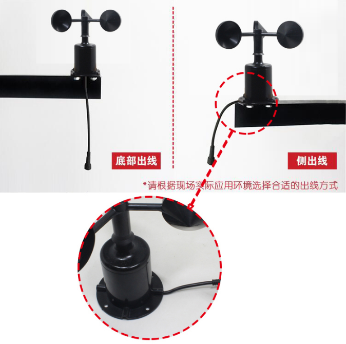
Adopt the bottom-out line mode, completely eliminate the aging problem of the aviation plug rubber pad, and still waterproof for long-term use.
High-performance imported bearings are used, with low turning resistance and precise measurement.
Polycarbonate shell, high mechanical strength, high hardness, corrosion resistance, no rust, can be used outdoors for a long time.
The equipment structure and weight are carefully designed and distributed, with a small moment of inertia and quick response.
Standard ModBus-RTU communication protocol, easy to access
1.2 Product structure appearance and size
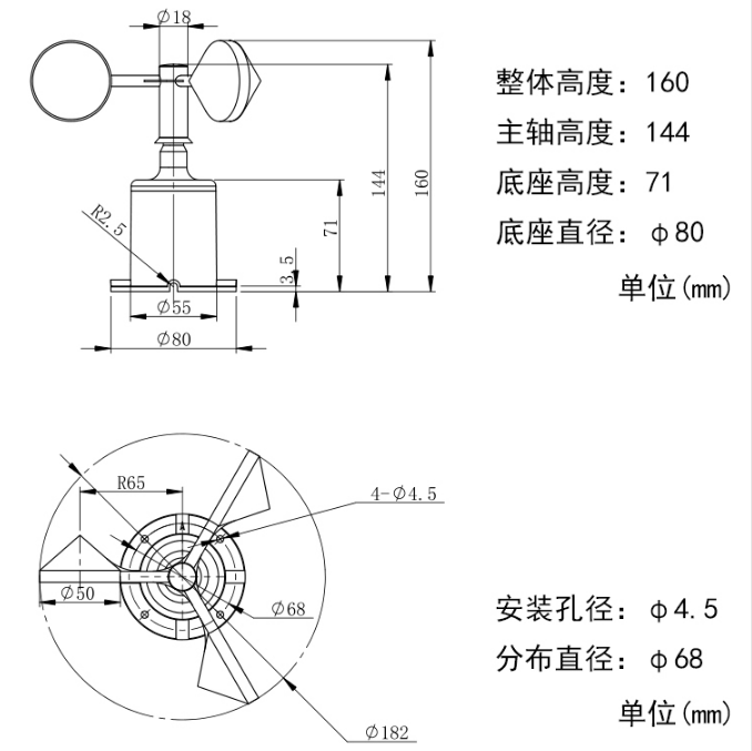
Product structure size diagram
1.3
Installation instructions
2.1 Unboxing Instructions
Please carefully open the packaging, ensuring that the packaging box and equipment are not damaged. Check the label on the packaging box to confirm that the product model and serial number match your order.
Please fully open the packaging box and check if it contains the following accessories:
|
Serial number |
Category |
Part name |
Quantity |
Unit |
|
1 |
Standard equipment |
Anemometer transducer equipment |
1 |
Table |
|
2 |
Installation screws |
4 |
person; people; individual; one; each; |
|
|
4 |
Product description |
1 |
portion |
|
|
5 |
Certificate of Conformity |
1 |
portion |
|
|
6 |
Warranty card |
1 |
portion |
|
|
8 |
Optional |
USB to 485 |
1 |
Root |
|
9 |
485 Terminal resistor |
1 |
person; people; individual; one; each; |
2.2 Wiring Instructions
2.2.1 Interface Description
Wide voltage power input of 10~30V is available. When connecting the 485 signal line, note that the A\B two lines cannot be connected in reverse, and the addresses of multiple devices on the bus cannot conflict.
2.2.2 Line sequence description
|
Color line |
Explanation |
|
|
Power supply |
Brown |
Power positive (10~30V DC) |
|
Black |
Power negative |
|
|
Communication |
Yellow (green) |
485-A |
|
Blue |
485-B |
2.3 Installation instructions
2.3.1 Installation method
The wind direction sensor is firmly fixed to the flange by means of a threaded flange connection, the base Ø80mm, with four mounting holes Ø4.5mm evenly distributed on the circumference of Ø68mm, which are tightly secured to the bracket with bolts, ensuring that the entire instrument maintains the best levelness, ensuring the accuracy of the wind direction data, the flange connection is convenient to use and can withstand a large pressure.
2.3.2 Installation Notes
The user must not disassemble it by himself, and must not touch the sensor core, so as not to damage the product.
Stay as far away as possible from high-power interference devices to avoid inaccurate measurements, such as frequency converters, motors, etc. When installing or removing the transmitter, the power supply must be disconnected first. Water entering the transmitter can cause irreversible changes.
Prevent chemical reagents, oil, dust, etc. from directly affecting the sensor, do not use it for a long time in a dew point environment, and strictly prevent sudden cold and heat.
Debugging configuration instructions
3.1 Debugging Tools Acquisition
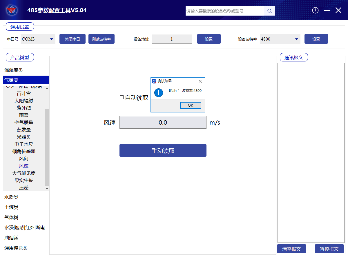
Contact the manufacturer's technical engineer to obtain the "485 parameter configuration software" Open it directly.
3.2 Parameter setting
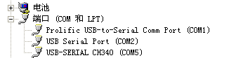
①Select the correct COM port ("My Computer - Properties - Device Manager - Ports" to view the COM ports), the following figure lists the drive name of several different 485 converters.
②Connect only one device and power it on, click the test baud rate in the software, the software will test the current device's baud rate and address, the default baud rate is 4800 bit/s, and the default address is 0x01.
③Modify the address and baud rate according to the usage needs (it is recommended to modify the baud rate to 9600), and you can also check the current functional status of the device.
④If the test is not successful, please re-check the equipment wiring and the installation of the 485 drive.
Communication protocol
4.1 Basic parameters of communication
|
Encoding |
8-bit binary |
|
Data bit |
8-bit |
|
Parity bit |
None |
|
Stop bit |
1 person |
|
Error checking |
CRC (Cyclic Redundancy Code) |
|
Baud rate |
2400bit/s, 4800bit/s, 9600 bit/s can be set, the factory default is 4800bit/s |
4.2 Data Frame Format Definition
Adopt ModBus-RTU communication protocol, format as follows:
Initial structure ≥4 bytes time
Address code = 1 byte
Function code = 1 byte
Data area = N bytes
Error checking = 16 bit CRC code
Ending structure ≥4 bytes time
Address code: The address of the transducer, which is unique in the communication network (factory default 0x01).
Function code: The function code indicates the command issued by the host, and this transducer only uses function code 0x03 (read register data).
Data area: The data area is specific communication data, note that the high byte of 16-bit data is in front!
CRC code: a two-byte checksum.
Host Inquiry Frame Format:
|
Address code |
Function code |
Register start address |
Register length |
Check code low order |
Check code high bit |
|
1 byte |
1 byte |
2-byte |
2-byte |
1 byte |
1 byte |
From the machine response frame structure:
|
Address code |
Function code |
Number of effective bytes |
Data area one |
Second data area |
The Nth data area |
Check code |
|
1 byte |
1 byte |
1 byte |
2-byte |
2-byte |
2-byte |
2-byte |
4.3 Register address
|
Register address |
PLC or configuration address |
Content |
Support function code |
Definition explanation |
|
0000 H |
40001 |
Instantaneous wind speed |
0x03/0x04 |
The uploaded data is 10 times the real value. |
|
07D0 H |
42001 |
Equipment address |
0x03/0x04/0x06 |
1~254 (factory default 1) |
|
07D1 H |
42002 |
Equipment Baud Rate |
0x03/0x04/0x06 |
0 stands for 2400 1 represents 4800 2 represents 9600 3 stands for 19200 4 represents 38400 5 represents 57600 6 stands for 115200 7 represents 1200 |
4.4 Communication protocol examples and explanations
Example: Reading the wind speed value from device address 0x01
Inquiry Frame:
|
Address code |
Function code |
Start address |
Data length |
Check code low order |
Check code high bit |
|
0x01 |
0x03 |
0x00 0x00 |
0x00 0x01 |
0x84 |
0x0A |
Response frame: (e.g. read the current wind speed as 8.6m/s)
|
Address code |
Function code |
Return the number of valid bytes |
Current wind speed value |
Check code low order |
Check code high bit |
|
0x01 |
0x03 |
0x02 |
0x00 0x56 |
0x38 |
0x7A |
Wind speed calculation:
Current wind speed: 0056H (hexadecimal) = 86 => Wind speed = 8.6m/s
Hardware parameters
|
DC power supply (default) |
10~30V DC |
|
Average power consumption |
0.3W |
|
Transducer circuit operating temperature |
-40℃~+60℃, 0%RH~80%RH |
|
Communication interface |
485 Communication (ModBus) protocol Baud rate: 2400, 4800 (default), 9600 Data bit length: 8 bits Parity check method: None Stop bit length: 1 bit Default ModBus communication address: 1 Support function code: 03/04 |
|
Parameter setting |
Configure via the provided configuration software over the 485 interface |
|
Resolution |
0.1m/s |
|
Precision |
±(0.2+0.03V) m/s V represents wind speed |
|
Measurement range |
0~70m/s |
|
Dynamic response time |
≤1s |
|
Material |
Polycarbonate material |
Long-term use, please keep the environmental wind speed below 30m/s
Wind Speed Sensor HC-FS100
Air speed Sensor (modbus 485 type)HC-FS100-01
Related products


")
")
")
Related products
Welcome to leave a message for consultation

Copyright © 2025 Xiamen Haichuan Runze Internet of Things Technology Co.,Ltd. ALL Rights Reserve.
Welcome to leave a message for consultation