
 Inquiry
Solution
Plan for Urban Pipeline Flow and Water Quality Monitoring System
In order to master the operation characteristics of rainwater and sewage pipelines, discharge outlets, open channels and rivers, it is necessary to measure a variety of basic operation parameters such as liquid level, flow rate and water quality, obtain continuous liquid level, flow rate and water quality data, master its change law, and through the instantaneous analysis, statistical calculation and model simulation of these basic data, the system can be comprehensively diagnosed and evaluated, and a solid data foundation can be laid for the development of various research work.
The online monitoring system of drainage pipeline and facilities should be expanded according to the actual situation, which can achieve the technical requirements such as design optimization, process control and operation dispatching of municipal drainage pipeline and facilities, and provide useful, effective and timely data support for the operation and management of municipal drainage pipeline and facilities.
Design principles:
①Online monitoring equipment should include level gauge, flow meter, water quality analyzer and other monitoring instruments.
②In accordance with the confidentiality system requirements stipulated by the state, collect, transmit, use and update the monitoring data of drainage pipelines and facilities, ensure that the data is not lost and not illegally used, and ensure data security.
③Consider the implementation conditions for equipment installation in the design of the scheme, and the selection and installation of monitoring equipment should adapt to the actual operation conditions of the drainage facilities, strengthen the testing, calibration, inspection and maintenance of monitoring equipment, and ensure the normal operation of the equipment.
④ Ensure proper training for on-site staff, who should understand the monitoring scheme and monitoring objectives, be familiar with the monitoring points and monitoring content, and be proficient in the technical requirements for equipment installation and operation and maintenance. The principle of safety first and prevention foremost should be adhered to, and the health and safety of the staff should be ensured.
⑤Establish a long-term operation and maintenance guarantee mechanism for the drainage pipeline network and facilities monitoring system to ensure the long-term effectiveness of monitoring equipment and data management platform.
System composition:
The system integrates advanced technologies such as modern sensor technology, Internet of Things technology, mobile communication technology, data warehouse technology, and automation control, achieving automatic collection, online dynamic monitoring, real-time monitoring management, auxiliary decision-making, and emergency response management of hydrological and water quality information of drainage pipelines.
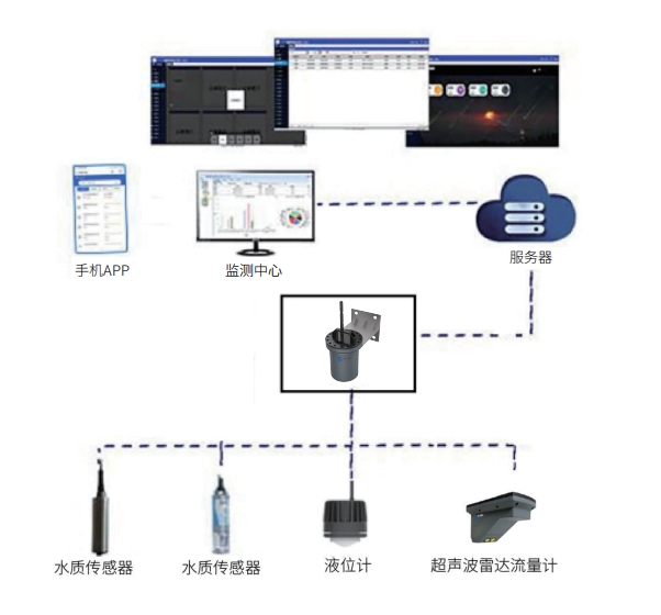
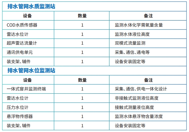
The drainage pipeline flow and water quality monitoring system consists of the following main parts:
1、Flow rate flow sensor, water quality sensor;
2、Pipeline data collection host: The function is to provide long-term power supply, implement power management for sensors to achieve low-power monitoring operation, and at the same time, the device is equipped with a built-in 4G communication module to achieve data conversion and transmission from the industrial bus to the Ethernet.
3、Information management platform: provides project site management, receives monitoring data and stores and displays it, statistical analysis, downloads and expands various business applications.
4、Installation accessories: special brackets for equipment installation, flow cards, and supporting commissioning tools, etc.
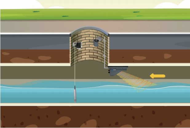
Site installation diagram:
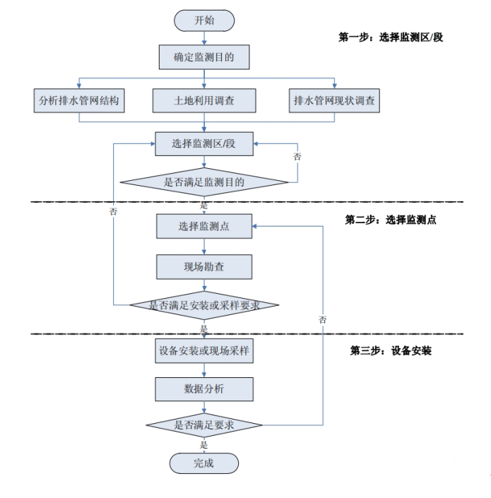
Monitoring station construction process flow chart:
Traffic monitoring requirements are as follows:
The collection frequency and upload frequency of the Internet of Things monitoring equipment can be customized. In this project, the collection frequency and upload frequency are both once every 4 hours.
Facility deployment requirements:
1. The municipal drainage department should plan and deploy the installation points of online monitoring instruments uniformly, and the collected operation data of the drainage pipeline can meet the needs of the operation state analysis and management of the drainage facilities.
2、Online monitoring instruments should be confirmed for site environment before installation to ensure compliance with equipment installation conditions.
3、Check the name, model, specification, and appearance of the instrument before installation, and read the relevant accessories and technical documents carefully.
4、The safety technical measures during construction shall conform to the current industry safety production specifications, and the installation process flow shall be formulated when installing complex instruments to ensure construction safety.
5、Instruments should be installed away from mechanical vibration, strong electromagnetic fields, medium corrosion, and high temperatures.
6、The instrument shall not be knocked or vibrated during installation, and shall be firmly and vertically installed after installation, without bearing any external force from the pipeline or other machinery.
7、The fasteners used for the installation of online monitoring instruments shall be stainless steel products, except for the anchor bolts.
8、The installation process should not break the road, interrupt the flow, or go down the well, and the monitoring equipment should be installed, convenient, and properly deployed.
Main equipment selection, parameters:
COD Water Quality Sensor: Optical method measurement, no reagents, no pollution. The deep ultraviolet beam is absorbed by organic matter dissolved in water during the transmission process, and the absorption degree is proportional to the concentration of organic matter, thus the content of organic pollutants in the sample can be evaluated by measuring the absorbance of the deep ultraviolet beam.
1、COD range of measurement: 0~600mg/L equiv.KHP
2、COD accuracy: ±5% F.S
3、COD resolution: 0.1mg/L
4、TOC range: 0~240mg/L equiv.KHP
5、TOC accuracy: ±5% F.S
6、TOC resolution: 0.1mg/L
7、Turbidity range: 0~300NTU
8、Turbidity accuracy: ±5% F.S
9、Turbidity resolution: 0.1NTU
10、Working temperature: 5~40℃
11、Maximum depth: 10 meters below the surface
12、Digital interface: MODBUS/RS485
13、Simulated interface: 4-20mA
14、Power supply: 12~24VDC
15、Power consumption: Normal power: <0.5W
16、Calibration: single point/two points/three points calibration
17、Protection level: IP68
18、Installation method:流通 pool installation, immersed installation, 3/4″NPT thread
19、Size; Φ34*232mm
20、Material: 316 stainless steel
Radar Water Level Meter: This radar uses FMCW mode, non-contact installation design, small and exquisite in size, compact in structure, high in precision, low in power consumption, and strong in anti-interference ability. It is suitable for water level monitoring in lakes and rivers, mountain flood warning, water storage pools, sewage pipelines, etc.
1、Emission frequency: 76GHz~81GHz
2、Resolution: 1mm
3、Measurement range: 0.15 - 40m
4、Measurement accuracy: ±5mm
5、Beam angle: horizontal 6°/vertical 6°
6、Working voltage: 9~24V
7、Communication method: RS485
8、Working temperature -40-85℃
9、Working current: 20mA@12V
10、Boot time: 100ms
12、Protection level: IP68
13、Dimensions (diameter*height): 66x96mm
Ultrasonic radar flow meter: The product integrates the advantages of radar flow measurement and ultrasonic flow measurement. When the pipeline is not full, radar is used to monitor the flow rate and water level. When the pipeline is full, a pressure-type water level meter is used to measure the water level, and ultrasonic is used to measure the flow rate, achieving full-pipe and non-full-pipe all-scene flow measurement.
1. Supply voltage: DC12V/24V
2、Working current: 500mA DC12V
3、Working temperature: -20℃~75℃
4、Dimensions: 207.0*108.6*109.5(mm)
5、Communication interface: RS485
6、Protection level: IP68
7、Radar flow measurement frequency band: 60GHz
8、Radar beam angle: 16*20°
9、Radar speed measurement range: 0.1-20m/s
10、Radar speed accuracy: 0.01m/s
11、Radar range measurement range: 0.1-50m
12. Radar range accuracy: ±2mm
13、Radar range resolution: 1mm
14、Ultrasonic speed measurement range: 0.021-6m/s
15、Ultrasonic speed measurement accuracy: ±1.0%FS±1cm/s
16、Ultrasonic water level range: 0.03-5m
Communication Power Supply Unit: integrated design, combining RTU, display, cabinet, communication, and power supply system to realize the comprehensive functions of data collection, storage, power supply, display, transmission, and alarm. Industrial-grade design: wide temperature design, resistant to high and low temperatures, and strong electromagnetic interference, suitable for various harsh field environments.
1. Communication method: 4G full network;
2、Built-in battery: ultra large capacity 152Ah
3. Multi-center Reporting: Supports multi-data center and primary/standby data center reporting functions, up to 4 centers.
4、Display: Support local LCD screen to view pressure, flow, water level and other monitoring data
5、Output power supply: provides a controllable 12V@100mA output power supply
6、485 interface: 1 RS485 interface, built-in 15KV ESD protection
7、Analog interface: 2 channels of analog input interface (16-bit AD, supports 4-20mA current signal input, optional 0-5V voltage signal input)
8、Switching quantity interface: 2 channels of switching quantity input interface (optical isolation)
Logic 0: Wet node 0-3VDC, or dry node conductive
Logic 1: Wet node 5-30VDC, or dry node open
9、2nd controlled output power supply (12V/1A rated power with built-in overcurrent protection) 12V/100mA
10、Power consumption: operating <60mA@DC7.2V(avg current); sleep ≤40uA@DC7.2V
11、Case protection level: ABS+PC, IP68
12、Working temperature:-40~80ºC(-31~167℉)
13、Storage temperature: -40~85ºC(-40~185℉)
14、Screen operating temperature: -20~70ºC(-4~158℉)
15、Screen storage temperature: -30~80ºC(-22~176℉)
16. Relative humidity: 95% (no condensation)
Pressure Water Level Meter: The equipment uses imported sensor cores from abroad, which convert liquid level pressure signals into corresponding digital signals, and then process them through digital circuits to output standard signals such as 4~20ma and RS485. The product has the characteristics of compact structure, robustness, corrosion resistance, overload protection, and convenient use.
1. Range: 0m~10m~30m~100m optional
2. Pressure types: gauge pressure or absolute pressure
3、Accuracy: ±0.2%FS
4、Adapt to the rate of water level change: ≤40cm/min
5、Response frequency: Digital signal output ≤ 5Hz
6、Medium temperature: -35~85℃(常温 type)
7、Working voltage: 10~36V DC Standard DC12V
8、Output signal: RS485
9、Protection level: IP68
10. Shell: Stainless steel 1Cr18Ni9Ti
Suspended Matter Sensor: The content of suspended matter in water is one of the indicators to measure the degree of water pollution. The device adopts optical measurement method, no chemical reagents are required; built-in temperature transducer, with automatic temperature compensation function; using modulated light signal, reducing the interference of visible light; can be widely used in water treatment, aquaculture, environmental monitoring and other industries.
1. Power supply: DC12V
2、Power consumption: <0.5W
3、Communication interface: RS485; Standard ModBus-RTU protocol;
4、Measurement principle: light scattering method
5、Measurement range: 0~ 3000mg/L;0~ 1000mg/L;0~ 200mg/L
6、Measurement error: ±8% F.S. (depending on the homogeneity of the water body)
7、Measurement resolution: 0.1mg/L
8、Response time: ≤30s
9、Equipment working conditions: 5~40℃
10、Waterproof rating: IP68
11、Pressure resistance: 5 meters underwater
12、Case material: corrosion-resistant plastic, stainless steel
Integrated manhole monitoring terminal: The device integrates 4G/NB-IOT wireless communication modules, large-capacity lithium batteries, and data collection and storage functions. It has an IP68 protection level and is widely used in online network monitoring applications of urban sewage wells, drainage wells, rivers, and reservoirs in water conservancy and hydrological engineering.
1. Communication method: 4G full network;
2、Built-in battery: Support ultra-large capacity 152Ah 7.2V (non-rechargeable), 72Ah rechargeable 8.4V, 36Ah rechargeable 8.4V
3、Support for multi-data center, primary/standby data center reporting function, up to 4 centers
4. 485 Interface: 4 RS485 interfaces, built-in 15KV ESD protection
5、2-way controlled output power supply (12V/1A rated power with built-in overcurrent protection)
6、Built-in methane gas detection sensor
7、And inside and outside 2-way temperature and humidity sensor
8、Power consumption: operating <60mA@DC7.2V(avg current); sleep ≤40uA@DC7.2V
9、Support automatic additional reporting settings. (Automatically adjust the collection density if the set value is exceeded)
10、Remove the additional reporting mode. (If below the safe value, the collection density is automatically restored)
11、Remote upgrade, can be upgraded remotely through the server
12、Local serial port configuration and Bluetooth configuration.
13、Remote configuration, configuration parameters can be set through remote services.
14、Case protection level: ABS+PC, IP68
15、Working temperature: -40~60ºC (not chargeable)、-20~60ºC (chargeable)
16、Storage temperature: -40~85ºC(-40~185℉)
17 Relative humidity: 95% (no condensation)
Equipment construction and installation:
1. The preparation stage before the implementation
Before the implementation of the project, report the construction procedures to the relevant departments; formulate the site construction plan according to the site construction conditions, and carry out the design disclosure with the outsourcing construction team according to the construction drawings; arrange the construction schedule; order the main equipment and materials and the auxiliary materials for construction, prepare the construction environment, including temporary workshops and warehouses, power supply, etc., by Party A, and prepare the tools and testing instruments, arrange the work schedule, etc., by Party B.
2、On-site installation phase
Adopt standardized wiring and necessary shielding and safety protection measures to ensure that the wiring is reasonable and reliable, neat and beautiful, to ensure the effective transmission of signals and the simple and effective maintenance of the system; strive to improve the quality and flexibility of the transmission system, to facilitate system expansion and upgrading. According to the system design documents and the actual situation on site, the system equipment and devices are installed in a procedural and standardized manner without affecting the normal work of users, to ensure high quality while shortening the construction period as much as possible.
3. Debugging phase
System software commissioning before delivery; System hardware commissioning before delivery; Single unit commissioning of control equipment; Cold state commissioning of software and hardware at the construction site; Subsystem commissioning work; Integrated commissioning, etc.
4. Equipment installation precautions
①The equipment must be installed correctly to achieve the design function, read the equipment manual carefully and install it under the guidance of the engineer.
②Please check that the equipment is intact and all parts are present before installation.
③The support is designed and customized reasonably according to the actual construction situation of the pipeline network. The reserved installation hole positions of the support need to match the hole positions of the built-in support of the equipment.
④When handling the equipment, please ensure to handle it with care to avoid bumps and collisions with the equipment, otherwise it may affect the waterproof performance of the equipment or cause equipment failure and other issues.
Installation diagram:
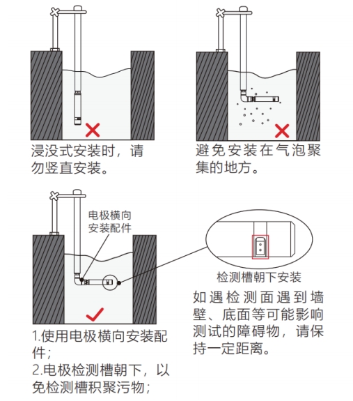
Installation example of water quality sensor
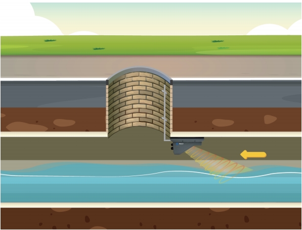
Ultrasonic radar flow meter installation diagram
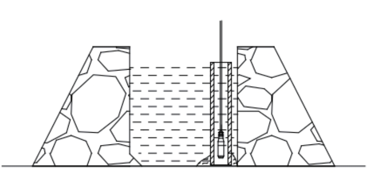
Installation of pressure water level gauge
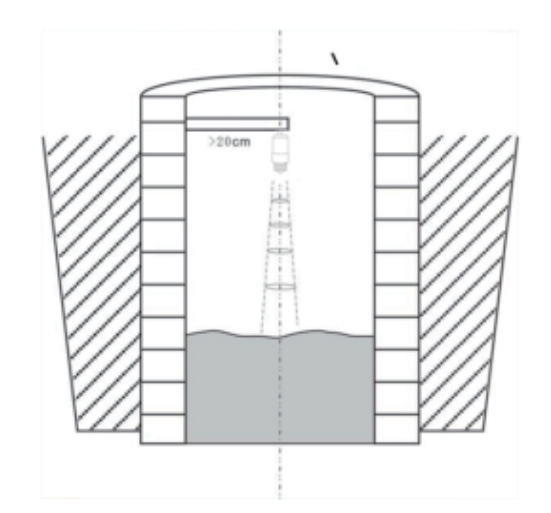
Radar water level meter installation illustration
Online monitoring equipment operation and maintenance:
1. Check the data operation situation every day, find the equipment with operation problems, and sort out the maintenance work list.
2. Formulate patrol inspection plans, carry out on-site patrol inspections and maintenance of monitoring equipment, check the working condition of online monitoring instruments, including whether the equipment has been stolen, whether the equipment is intact, whether the probe is intact, whether it is necessary to carry out dredging work, etc.; check whether the control equipment instruments, signal indicators are normal, whether the switch operation is flexible and reliable, whether the control is accurate, etc.
3、Regular cleaning of the impurities, trash, etc. deposited on the online monitoring instrument probe to ensure the normal operation of the probe and confirm that effective data can be obtained.
4、Check whether the parts of the online monitoring instrument are loose regularly, and consider the influence of the site temperature and humidity on its electronic parts, whether it is necessary to provide consumable replacement.
5、Formulate and implement the battery replacement strategy for the monitoring equipment based on the battery voltage of each monitoring equipment.
6、For the fault causes such as large parameter fluctuations (no signal, instantaneous flow or level, etc.), inconsistency between instantaneous flow and cumulative flow, unstable data, and data significantly exceeding the normal value range, it is necessary to eliminate them on site for online monitoring instruments.
7、Continuously observe the specific situation of the online monitoring data, observe whether the online monitoring data is stable and continuous, and preliminarily judge whether the online monitoring data is effective, diagnose the data abnormal situation, and carry out timely on-site repair.
8、The quality of monitoring data and the operation guarantee of equipment should meet the following requirements:
①The number of effective data collected daily is not less than 90% of the total number of data that should be collected;
②The proportion of abnormal data to the total number of data to be collected each day shall not exceed 10%. Abnormal data includes but is not limited to: non-normal zero value data, values outside the normal range, and strange values outside the normal range of variation, etc.
③ Ensure the continuous operation of the equipment and the acquisition system for 7×24 hours. The time for repair or replacement of equipment failure should not be greater than 24 hours.


Copyright © 2025 Xiamen Haichuan Runze Internet of Things Technology Co.,Ltd. ALL Rights Reserve.
Welcome to leave a message for consultation